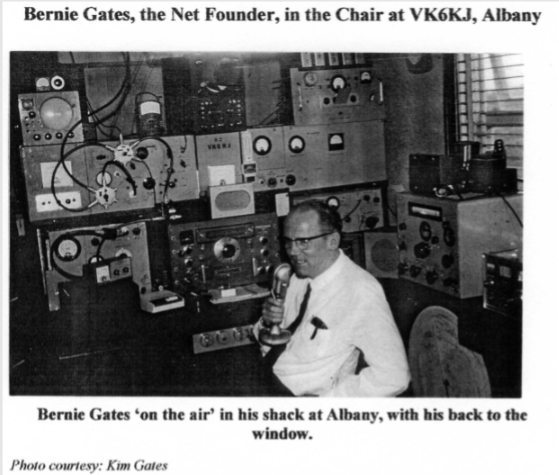
Bernie Gates Shavers Net.
Projects
Clive VK6CSW – Homebrew QRP Transmitter
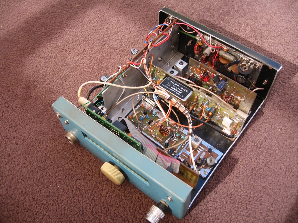
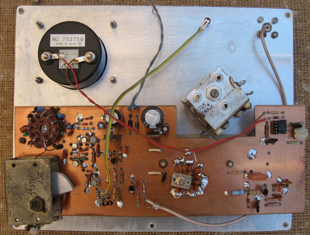
Boards from top left are: push-pull PA (should give about 8W pep); PA driver; CIO and DSB generator; IF board awaiting crystals, ssb output goes to driver and PA on tx and to rx audio amp on receive;
From bottom left: Audio output amp; mic amp; rx mixer board (output goes to IF board).
The advantage of modular construction is that any given stage can be rebuilt or upgraded as required, without disturbing all the other boards. It also makes signal tracing or level adjustments quite easy.
Chassis was folded up from a piece of scrap ali sheet. The long slot in the front is for the DDS LED readout while the oblong hole in the rear accommodates the PA heat-sink. Most of the other boards will be fitted to both sides of two vertical ‘slats’ running almost the length of the chassis. This makes removal or replacement quite easy and occupies less space than just putting the boards along the bottom of the chassis.
Ed. The original images to go with the above text have been misplaced. The project is now complete, see below…
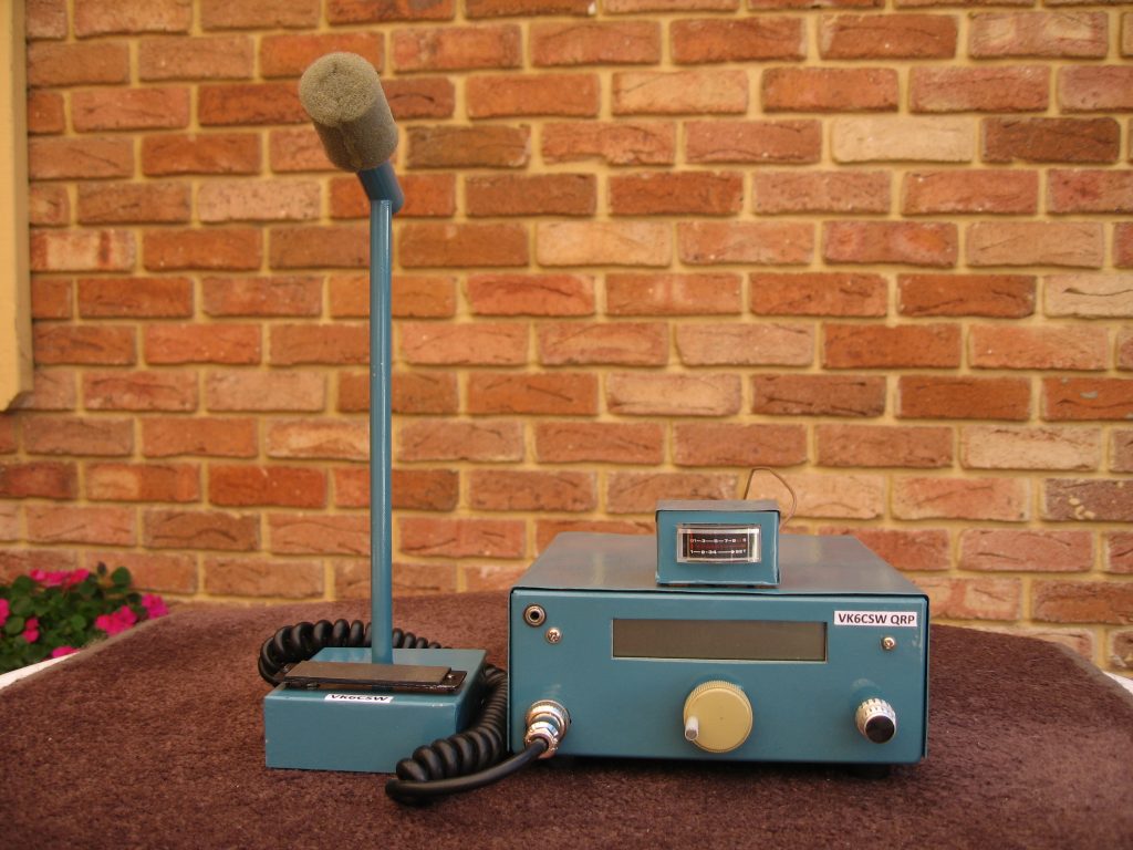
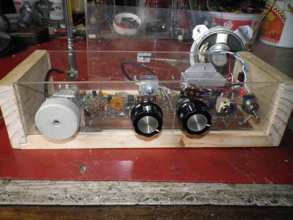
and of course you would like to see inside …
Clive prides himself in having a Shack that is substantially Home brew. Well done Clive!
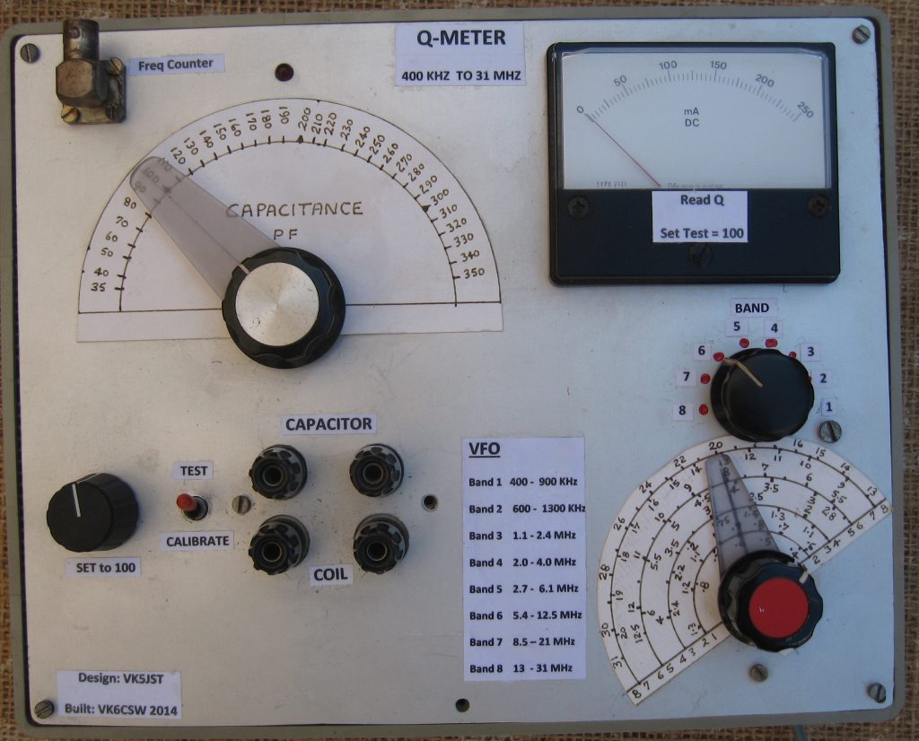
Here are a few images of some of his Test Gear..
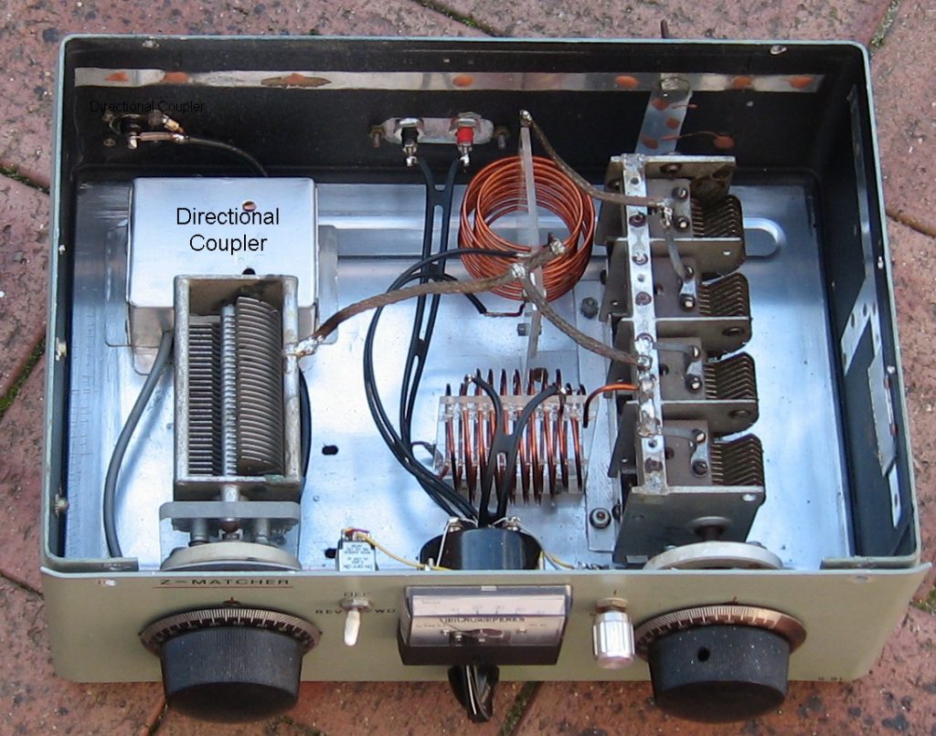
and look at this very nicely built Z Match
Ron VK6ARE..
Melody Maker Rebuild/Refurb
A brief overview of one of Ron’s ( VK6ARE ) recent projects. Ron’s email edited by Richard VK6BMW I just thought because of the interest in my little project that I would send you all a few pictures of the radio and tell a bit about it. First off I came by it quite some time back, about 1972 from a friend here in Bunbury . He knew that I had an interest in radio so offered it to me for nothing , mind you it wasn’t all that good to look at at the time , the mice and rats having had a wonderful time in it. In fact the wiring was mostly all gone or bare wire and the box was just one big rats nest, valves broken and lost, just think of the destruction and you have it, anyhow it goes now. The valves were originally 2 volt. However, because of the rarity, they are almost unprocurable and those that are available, priced beyond what I am prepared to pay. The 4 volt valves, given to me from Laurie’s (VK6GL) estate just the other day, were a good substitute and work very nicely with a little adjustment and base changes. The pix show the innards now . I have had to make up a power supply to supply the screen and anode voltages … 60V and 135v. The filament voltages I have provided from a small 12 volt battery via a LM317 regulator circuit , it will adjust from 2-10 volt . The sound on speech is really quite good with little to no hum from the AC supply. Filaments of course are pure DC. As for music, well that’s another story, not forgetting the set is nearly 100 yrs old! But, still it’s not all that bad. Well I hope I haven’t bored you with my pride and joy . Have a good day and catch you all tomorrow hopefully. Ron VK6ARE
Now for the interesting stuff….
Melody Maker from Cossor circa around 1929
Click on an image to enlarge…


and here is the VHF receiver..
VK6XO AM Transmitter
VK6XO – Ron
Ron sent this in :-
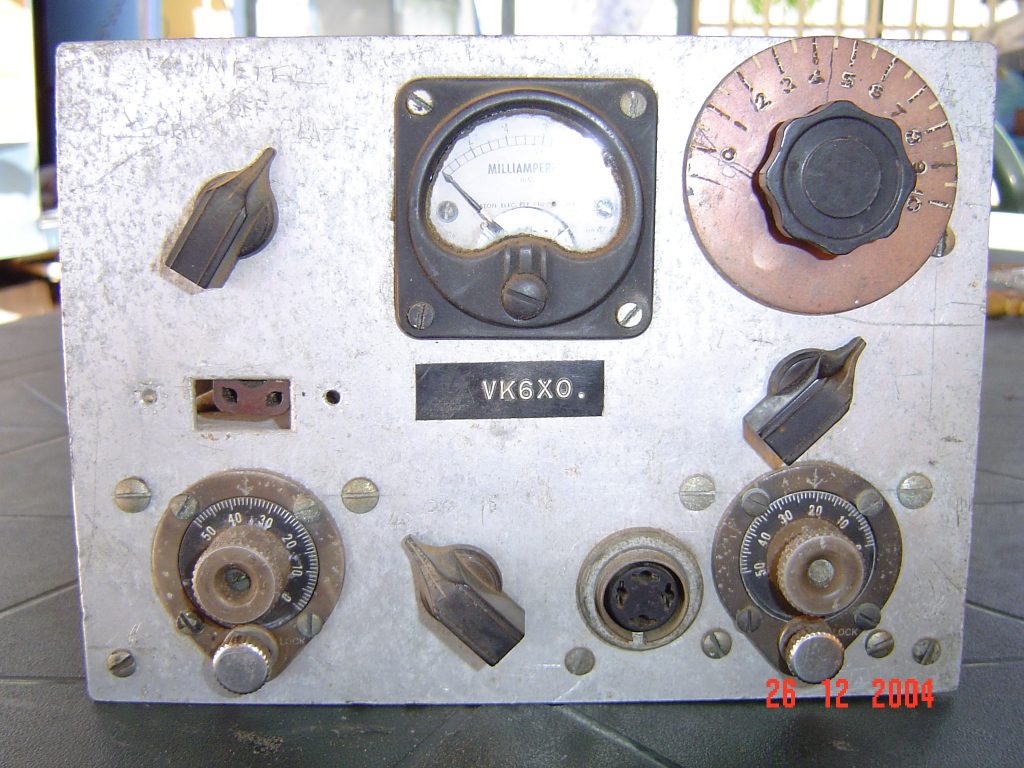
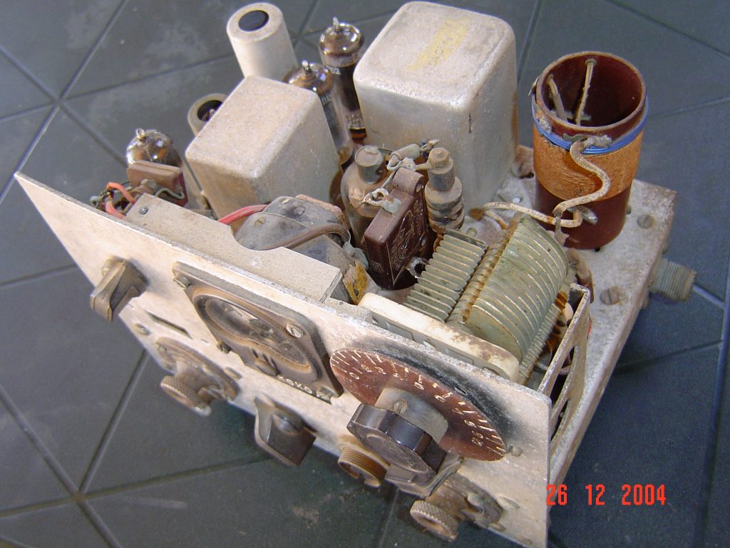
This was Dad’s ( VK6XO – Herb ) home brew AM TX using a 6L6 in the final which he operated mobile .
It was teamed with a Gelosso RX and an ex WW2 genemotor for HT.
The hole in the face panel on the left was where you inserted the Xtal for the operating frequency
Regards Ron VK6XO
Ed. Looks like a great restoration project for someone ?
![]()